
Members: Jeremy Brown, Xiyu Duan, Wajiha Shahid, Hongtao Wang
Project Description:
In this project we aim to study the performance and stability trade-off of a haptic based teleoperator. Performance will be measured in terms of the teleoperator's transparency, which is a measure of how accurately the master device replicates the interactions sensed between the slave and a remote environment. Our teleoperator consist of two Novint Falcon 3DOF closed chain manipulators. We are controlling the devices using Microsoft Visual Studio 2008 and the following source code found here (link to source code). The devices are controlled in a position-postion control architecture. We would like to determine the effect of varying control methods (P, PI, PD, PID) on the system's transparency. In order to measure transparency, we will perform system identification experiments looking at the frequency response of our teleoperator. We will use force as input to both the master and slave devices and measure velocity on both devices.
In addition we will asses the devices ability to render haptic virtual environments.
Objectives:
- Develop teleoperator communication link between two Falcon devices
- Develop proportional controller (P control)
- Develop proportional-derivative controller (PD control)
- Develop proportional-integral controller (PI control)
- Develop proportional-integral-derivative controller (PID control)
- System Identification Experiments
- Force input (master); Velocity output (slave)
- Force input (master); Velocity output (master)
- Force input (slave); Velocity output (master)
- Force input (slave); Velocity output (slave)
- Develop a model for the two-falcon teleoperator
Picture and movie:
Teleoperator Demo
Teleoperator transfer function measurement
Model, including Jacobian:
The Jacobian can be computed to relate the task space velocities and joint space velocities. The following schematic depicts the basic kinematics of the Falcon device.
Teleoperator Demo
Teleoperator transfer function measurement
Model, including Jacobian:
The Jacobian can be computed to relate the task space velocities and joint space velocities. The following schematic depicts the basic kinematics of the Falcon device.


The Jacobian matrices relates the joint and the end effector velocities as follows:
 where
where

The manipulator Jacobian for the closed chain Falcon device can be computed as
 We did not directly compute the Jacobian in our code to develop the forward and inverse kinematics, instead, the Jacobian was accounted for in the implementation of gravity compesnation. The main objective of incorporating gravity compensation was to 'add' more mass to the Falcon devices such that the devices would remain in whichever configuration they were placed in rather than falling under their own weight. Experiments with both Falcon devices proved that the fidelity of the Falcon device was substantially improved when gravity compensation was added.
 variable discussion
Block Diagram:

Controller Design


Implementation Notes:
The code is developed based on the CHAI 3D library, in which we used to display the location of the end effector. For some reason, the CHAI 3D library is not working properly if two falcons are connected at the same time. So we decided to use the HDAL Api directly. HDAL Api is provided by Novint for Falcon related product development. To use HDAL in CHAI 3D library, the code is in the following link.
http://code.google.com/p/falcon-teleoperation/
To estimate the impedance of each falcon, we injected force into each one and measure the output velocity. Then we did a model fitting to the curve and calculated the overall transfer functions for the two-falcon teleoperator.
Results:
Transfer function (H11):
22.02 s^5 + 4143 s^4 + 5.421e05 s^3 + 4.041e07 s^2 + 1.987e09 s + 5.4e10
------------------------------------------------------------------------
s^6 + 304.1 s^5 + 5.508e04 s^4 + 5.021e06 s^3 + 2.998e08 s^2 + 8.63e09 s
Transfer function (H12):
-21.98 s^5 - 4131 s^4 - 5.401e05 s^3 - 4.028e07 s^2 - 1.98e09 s - 5.4e10
------------------------------------------------------------------------
s^6 + 304.1 s^5 + 5.508e04 s^4 + 5.021e06 s^3 + 2.998e08 s^2 + 8.63e09 s
Transfer function (H21):
-21.98 s^5 - 4131 s^4 - 5.401e05 s^3 - 4.028e07 s^2 - 1.98e09 s - 5.4e10
------------------------------------------------------------------------
s^6 + 304.1 s^5 + 5.508e04 s^4 + 5.021e06 s^3 + 2.998e08 s^2 + 8.63e09 s
Transfer function (H22):
22.02 s^5 + 4143 s^4 + 5.421e05 s^3 + 4.041e07 s^2 + 1.987e09 s + 5.4e10
------------------------------------------------------------------------
s^6 + 304.1 s^5 + 5.508e04 s^4 + 5.021e06 s^3 + 2.998e08 s^2 + 8.63e09 s


Discussion:
Block Diagram:

Controller Design
Since we are using position-position control for the teleoperator, a good controller is very important. Since the two devices are almost the same, we will use the same controller for both the master side and the slave side. To choose a good controller, we turn the PID parameters for a single falcon device first.
If we only use P controller and feed sinusoids with different frequencies as desired trajectories, the results for different Kp values are shown below:
Kp = 50


Kp = 100

Kp = 200

Kp = 300

Kp = 400

Kp = 500

Kp = 600

If we use PD controller and feed sinusoids with different frequencies as desired trajectories, the results for different Kp and Kd values are shown below:
Kp = 700, Kd = 10

Kp = 700, Kd = 20

Kp = 700, Kd = 30

If we se PID controller and feed sinusoids with different frequencies as desired trajectories, the results for different Kp, Ki and Kd values are shown below:
Kp = 500, Ki = 4, Kd = 10

Kp = 500, Ki = 4, Kd = 20

Kp = 700, Ki = 2, Kd = 20

Kp = 700, Ki = 3, Kd = 20

Demo:
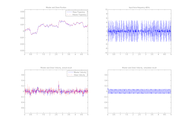
Plot of the master and slave trajectories:

Implementation Notes:
The code is developed based on the CHAI 3D library, in which we used to display the location of the end effector. For some reason, the CHAI 3D library is not working properly if two falcons are connected at the same time. So we decided to use the HDAL Api directly. HDAL Api is provided by Novint for Falcon related product development. To use HDAL in CHAI 3D library, the code is in the following link.
http://code.google.com/p/falcon-teleoperation/
To estimate the impedance of each falcon, we injected force into each one and measure the output velocity. Then we did a model fitting to the curve and calculated the overall transfer functions for the two-falcon teleoperator.
Results:
 |
| 1/Zm = 1/Zs where Zm=Zs is the impedance of the Falcon device. Experimental data (blue), model (red) |
 |
| Transfer function between input force and output velocity |
 |
| Transfer function between input force and output velocity (detail) |
Transfer function (H11):
22.02 s^5 + 4143 s^4 + 5.421e05 s^3 + 4.041e07 s^2 + 1.987e09 s + 5.4e10
------------------------------------------------------------------------
s^6 + 304.1 s^5 + 5.508e04 s^4 + 5.021e06 s^3 + 2.998e08 s^2 + 8.63e09 s
Transfer function (H12):
-21.98 s^5 - 4131 s^4 - 5.401e05 s^3 - 4.028e07 s^2 - 1.98e09 s - 5.4e10
------------------------------------------------------------------------
s^6 + 304.1 s^5 + 5.508e04 s^4 + 5.021e06 s^3 + 2.998e08 s^2 + 8.63e09 s
Transfer function (H21):
-21.98 s^5 - 4131 s^4 - 5.401e05 s^3 - 4.028e07 s^2 - 1.98e09 s - 5.4e10
------------------------------------------------------------------------
s^6 + 304.1 s^5 + 5.508e04 s^4 + 5.021e06 s^3 + 2.998e08 s^2 + 8.63e09 s
Transfer function (H22):
22.02 s^5 + 4143 s^4 + 5.421e05 s^3 + 4.041e07 s^2 + 1.987e09 s + 5.4e10
------------------------------------------------------------------------
s^6 + 304.1 s^5 + 5.508e04 s^4 + 5.021e06 s^3 + 2.998e08 s^2 + 8.63e09 s
Simulink model, with Fm Fs as input and Vm Vs as output.
 |
| Simulink Model of the two-falcon teleoperator |
Comparison of the simulation result of the two-falcon teleoperator with the actual result. The input forces are 10-60Hz sinusoid.


In conclusion, we have a really good model for the two-falcon teleoperator!
Discussion:
The objective of the forward kinematics solution is to define a mapping from the known set of actuated joint angles to the unknown position of the moving platform. The kinematic analysis for the Falcon device involves obtaining the loop closure equations for each leg and then reducing the equations to two 16th degree equations in two unknowns. Several elimination approaches (Dialytic Elimination, Polynomial Continuation, Grobner bases, etc) can be used to eliminate one of the two unknowns from the two closed loop equations. For instance, the Dialytic method leaves a single 32nd degree equation in a single unknown once the two closed loop equations are simplified. Of the 32 solutions generated by this method, 16 are extraneous.
The inverse kinematics problem is defined as a mapping from a given position of the moving platform to the set of joint angles that allows the platform to achieve that position. For the Falcon device, the inverse kinematics can be derived by producing a set of three joint angles for each leg that define the possible postures for each leg for a given position of the moving platform. The solution for the manipulator consists of four solutions for each leg for a given position of the moving platform, where each real solution corresponds to a unique position of the leg.
We did not derive the forward and inverse kinematics for the Falcon configuration due to the complexity of the calculations involved. Instead the source code automatically computes the kinematics using numerical methods such as the Newton Raphson method for forward kinematics.
 |
| Magnitude plots of H matrix |
the blog is nice.im really enjoyed the above information.the information is mainly based on studying.Thanks for this.
ReplyDeleteRPA Training in Chennai
Robotics Process Automation Training in Chennai
RPA course in Chennai
Blue Prism Training in Chennai
UiPath Training in Chennai
UiPath Training Institutes in Chennai